AD-AB 12 WG, AD-AB 24 WG, AD-AB 32 WG

Description

The detached connection block AD-AB 12/24/32 has been specially developed for the LMB Vario series of devices. The bus version of the Vario illuminated indicator has no input terminals and is therefore controllable exclusively via the RS485 bus. The detached connection block AD-AB 12/24/32 can be connected at this bus connection. This bus connection has active inputs, which are transmitted to the indicator light via its RS485 bus. With this, the Vario illuminated indicator can be configured via the configuring software ADStudio and behaves as if it had physical inputs. If the illuminated indicator is located in the control cabinet door or in the control centre, then the connection block can be easily mount on the hat rail in the control cabinet on site. The external connection block is available in three different variants. With 12, 24 and 32 inputs. The connection block has a short-circuit-proof supply voltage, with which contacts can also be supplied and therefore queried. Furthermore, an efficient switching power supply has been fitted, which works in a wide supply voltage range.
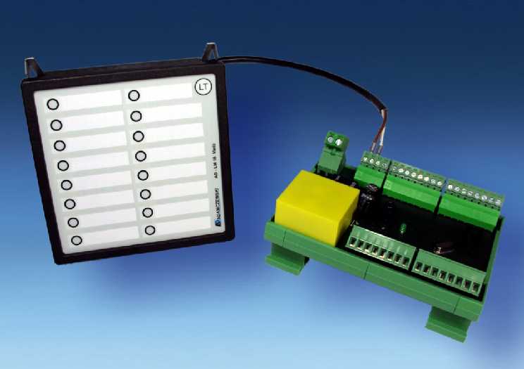
AD-AB 12 WG, AD-AB 24 WG, AD-AB 32 WG

Application

Application in connection with the Vario bus illuminated indicators (AD-LMB 6, AD-LMB 12, AD-LMB 16). When messages are to be indicated spatially separated from the control cabinet, a substantial amount of wiring can be saved here.

Specific characteristics

  • available with 12, 24 or 32 inputs
  • RS485 Bus connection to the indicator lights
  • Allpower supply
  • short-circuit proof feeding voltage
  • mouting on DIN rail

Business data

Order number
AD-AB 12 (12 Inputs)
AD-AB 24 (24 Inputs)
AD-AB 32 (32 Inputs)
Identifiers
Customs tariff number / country of origin 8543 70 90 / Deutschland

Information

Downloads
Data sheet pdf en-ab12_24_32.pdf (156 kB)
Safety instructions pdf ad-safety-instructions.pdf (43 kB)

Technical specifications

Active inputs
Voltage range 5 ... 30 V DC
Input resistance > 45 kOhm
Supply
Supply voltage 20 ... 253 V AC/DC
Max. power consumption 0,3W / 0,6VA
Feeding voltage for contacts
Voltage 4,8 ... 5,2 V DC
Strength Max. 1 mA
RS485 Bus
Cable length (screened) Max. 100 m
(terminator is integrated)
Send interval input data Ca. 100 ms
Housing
Dimensions (WxHxD) 113x82x54 mm
Type of protection IP 10
Connection method Terminal clamp / optionally detachable terminal clamp
Manner of fastening DIN rail housing
Calmping torque- RM 5 0,5 Nm
Clamping torque- RM 3,81 0,25 Nm
Weight 150 g
Environmental conditions
Ambient temperature -10 ... 50 °C
Storage and transport -10 ... 70 °C (no condensation)
EMC
Product family standard EN 61326-1
Emitted interference EN 55011, CISPR11 Cl. B, Gr. 1
Electrical safety requirements
Product family standard EN 61010-1
LEDs
Power- LED (green) On: power supply OK
Off: power supply error
Data- LED (yellow) Blinking: data connection OK
On/Off: data connection error
Terminal assignment
Clamp Connection name
U1 Supply voltage
U2 Supply voltage
B1 RS485 Bus clamp B
B2 RS485 Bus clamp A
G GND of the device
SP Supply Voltage for contacts
1 Input 1
2 Input 2
3 Input 3
4 Input 4
5 Input 5
6 Input 6
7 Input 7
8 Input 8
9 Input 9
10 Input 10
11 Input 11
12 Input 12
13 Input 13
14 Input 14
15 Input 15
16 Input 16
17 Input 17
18 Input 18
19 Input 19
20 Input 20
21 Input 21
22 Input 22
23 Input 23
24 Input 24
25 Input 25
26 Input 26
27 Input 27
28 Input 28
29 Input 29
30 Input 30
31 Input 31
32 Input 32

Block and wiring diagram

AD-AB 12 WG, AD-AB 24 WG, AD-AB 32 WG

Dimensions

AD-AB 12 WG, AD-AB 24 WG, AD-AB 32 WG

CAD / CAE Daten

CAD model is not yet available for this product.

The CAD product overview can be found at: adamczewski.partcommunity.com

Cookie settings
made with ♡ by andres.media