AD-FM 255 GVD, AD-FM 255 GVD-O

Description

The frequency measuring converter AD-FM 255 GVD supplies an initiator or a contact and transforms its impulse sequence to a proportional impressed analogue signal. The output signal is independent from the connected load up to a maximum value. All measuring ranges and outputs can be freely parameterized. This can be carried out via the optional operating panel AD-VarioControl or via the programming software AD-Studio. Input, output and the supply voltage are separated from each other galvanically with high isolation.
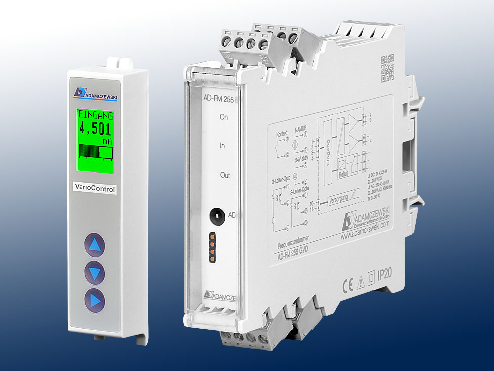
AD-FM 255 GVD, AD-FM 255 GVD-O

Application

The main area of application is the through-flow measuring at water meters, further applications are energy consumption measuring etc.

Specific characteristics

  • Inputs: NAMUR, contact, open collector, 3-conductor Opto, 24V activ
  • Outputs: current and voltage
  • Digital output: Relay or semiconductor (pulse or limit value function)
  • Operating module VarioControl as an accessory
  • Programming via configuration software

Business data

Order number
AD-FM 255 GVD Relay output
AD-FM 255 GVD-O Semiconductor output
Accessory (optional)
Operating module AD-VarioControl
USB programming adapter AD-VarioPass /AD-Studio
Identifiers
EClass 27210128
Customs tariff number / country of origin 8543 70 90 / Deutschland

Information

Downloads
Data sheet pdf en-fm255gvd.pdf (342 kB)
Tender text zip fm255gvd.zip (10 kB)
Operation manual VarioControl pdf man-variocontrol-ad-en.pdf (1 MB)
Safety instructions pdf ad-safety-instructions.pdf (43 kB)

Technical specifications

Digital input
Input NAMUR (EN 60947-5-6), reed contact, open-collector, 3-lead opto-transmitteror 24V active
Input frequency Min. 0 ... 10 mHz; max. 0 ... 10 kHz
Frequency generator supply Active: 8V / 8mA
Kontaktentprellung (activatable) 40 ms
Output current
Output range 0 ... 20 mA
Max. burden 400 Ohm
Residual ripple < 50 µAss
Output voltage
Output range 0 ... 10 V
Min. burden 10 kOhm
Residual ripple <20 µVss
Accuracy
Unit <0,3%
Temperature influence <100 ppm / K
Response time Approx. 70 ms
Relay output
Contact type Potential-free changeover
Max. AC-breaking capacity 250 V AC, 2 A AC, 50Hz
Max. DC-breaking capacity 50 V DC, 2 A DC
Switching operations
Mechanical 107
AC: 230V / 2A, cos(phi)=1 6 * 105
AC: 230V / 2A, cos(phi)=0,4 2 * 105
DC: 24V / 1A 2 * 105
Semiconductor output (optional)
Max switching voltage 30 V DC
Max. switching current 50 mA DC
Voltage drop < 1 V
Supply
Voltage range AC 50 ... 253 V AC, 50/60 Hz
Nominal voltage AC 230 V AC
Voltage range DC 20 ... 253 V DC
Nominal voltage DC 24 V DC
Power consumption AC / DC 3,7 VA / 2,1 W
Housing
Dimensions (WxHxD) 23x110x134 mm
With operating module (bxhxt) 23x110x138 mm
Type of protection IP 20
Connection method Detachable terminal clamp
Terminals, wire cross section 2,5 mm² flex wire / 4 mm² one wire
Bolting torque terminals 0,5 Nm
Weight ~ 140 g
Manner of fastening 35 mm DIN rail 35mm
Environmental conditions
Ambient temperature -10 ... 50 °C
Storage and transport -10 ... 70 °C (no condensation)
EMC
Product family standard 1) EN 61326-1
Emitted interference EN 55011, CISPR11 Cl. B, Gr. 1
In a critical EMC environment, shielded encoder cables are recommended.
1)During electromagnetic disturbance minor changes in output signal are possible.
Electrical safety requirements
Product family standard EN 61010-1
Overvoltage category II
Pollution degree 2
Galvanic isolation, test voltages
Input/output 2 kV RMS (1 min.)
Signal/auxiliary voltage 3 kV RMS (1 min.)

Block and wiring diagram

AD-FM 255 GVD, AD-FM 255 GVD-O

Dimensions

AD-FM 255 GVD, AD-FM 255 GVD-O

CAD / CAE Daten

Under "Generate CAD", select the desired CAD model for this product.
For this purpose, registration with our CAD database "PARTcommunity" is required.
The complete CAD product overview can be found at: adamczewski.partcommunity.com

AD-FM 255 GVD

Display and operating elements

On: LED for the power indicator in green
lights up - normal operation
flashing - signal failure, signal outside range limits
In: LED for input pulse signal
0 ... 7 Hz - according to signal
>7 Hz - 7 Hz flashing < br> Out: LED for the relays / semiconductor
lights up - relay energized
AD-PC: Communication interface for configuration by a PC
Communication interface VarioControl

Modbus Communication

The optional AD-VarioConnect operating module has an RS-485 interface. The data is transferred via the Modbus RTU protocol, the AD-VarioConnect operating module represents a Modbus slave. Communication takes place according to the master-slave procedure and starts with a request from the master, e.g. from a PLC or a PC. Each bus participant must have a unique address. If a slave detects that its address has been addressed by the master, the slave always sends an answer. The slaves never communicate with each other. They are also not able to start a communication with the master.
The Modbus master can read out the individual registers of the AD-FM 255 GVD via the addresses.
The default standard data format is 19200,e,8,1 with slave address 1. These settings can be changed via the AD-VarioConnect operating module.

Start address Number of registers Name Unit Data type read write

 Measured values:
40801 2 Input frequency Hz float 1 0
40803 2 Scaled input float 1 0
40805 2 Input percentage % float 1 0
40901 2 Output signal voltage V float 1 1
40903 2 Output signal current mA float 1 1

Cookie settings
made with ♡ by andres.media