1. Application area
Closed water heating systems with a nominal pressure up to 10 bar. For glass lined or
coated tanks with protective anode, an insulated version must be used.
APPLICABLE TO INSULATED VERSION ONLY: To prevent corrosion damage to glass lined or coated vessels
enameled or coated tanks, the tubular heating elements of the screw-in heating element are electrically insulated
the vessel and are connected in a defined conductive way via a resistor.
This increases the service life of the protective anode and the screw-in heating element.
2. Function
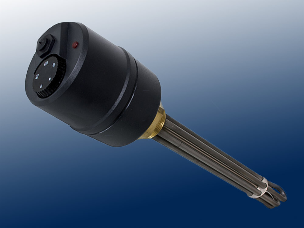
The sensors of the controller and the safety temperature limiter are located in a protective tube between the tubular heating elements. They detect the liquid temperature. The setpoint temperature can be adjusted. In the event of a fault, the safety temperature limiter switches the radiator off permanently.
3. Mechanical installation
The installation is carried out in threaded sockets G 1 ½ with suitable sealants. The length of the
threaded sleeve must always be smaller than the unheated zone (LU). The LU is indicated on the type plate. The thermally induced water circulation in the vessel must not be obstructed, e.g. by baffles.
4. Electrical connection
The screw-in heating element must be connected in conjunction with an RCD (FI) circuit breaker. The electrical
connection may only be done by an authorized specialist, the VDE 100 and the regulations of the local power supply company must be observed. To open, the controller knob must be pulled forward to the front / carefully lever it off. Then remove the two fastening screws of the cap.
- Wiring see circuit diagrams
5. Operating notes
Start-up should not be done until the tank is completely filled. If the STB responds, the cause of the fault must be determined.
After the cause of the fault has been eliminated, the STB can be reactivated by pressing the red button firmly after it has cooled down and the upper part of the housing has been removed.
Attention ! After professional installation, the STB provides sufficient overtemperature protection,
e.g. if the heating element runs dry. However, the STB is not a protection against dry operation. For this other protection systems such as level control systems or similar must be installed.
6. Additional functions (not existing in all heating elements)
- Signaling device: the light emitting diode signals that the device is heating
- External reset of the STB: after disconnection from the mains, the STB can be reset by removing the slotted screw in the upper part.
7. Maintenance
Before maintenance work, make sure that the mains supply is completely disconnected!
The heating element must be kept free of deposits and sediment. If the water contains lime, lime deposits can
malfunctions or even complete destruction of the screw-in heater due to lime deposits.
Regular inspection and decalcification is recommended.

