AD-LU 20 GT

Description

The digital power and energy meter AD-LU 20 GT measures all standard values of the three-phase system (active-, reactive-, apparent-power, voltage, currents, harmonics, power factor etc.) and provides this via an Ethernet interface. The measured values can be read out via Modbus-TCP protocol. In addition, these measured values are displayed on an integrated small WEB server. The device can also be parameterized via this WEB server. The AD-LU 20 GT is also equipped with an RS485 interface. This RS485 interface with Modbus-RTU protocol is mainly suitable for connecting an external display (AD-MM 400), but can also be used to read data or parameterize. The current is fed via the front-mounted through-current converters, which can measure up to 20 A directly. However, additional current transformers for larger currents can also be connected at any time. It is possible to measure symmetrical or unbalanced 4-wire networks and symmetrically loaded 3-wire networks. Due to the integrated, efficient wide-range power supply, the device operates in a large supply voltage range and does not heat up very much.
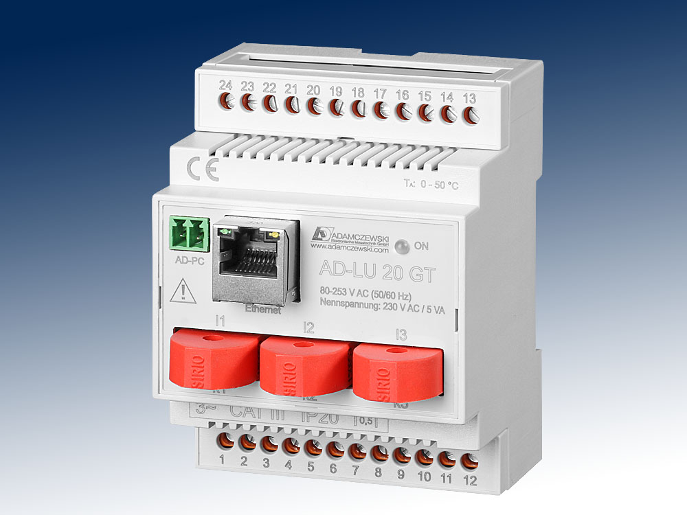
AD-LU 20 GT

Application

Measurement and monitoring of all electrical characteristics in electrical systems. Detection of load profiles for energy management systems, e.g. ISO 50001. Recording the energy consumption of individual consumers. Monitoring of voltage quality variables, e.g. harmonics.

Specific characteristics

  • internal current-transformer
  • Ethernet-Interface
  • RS485-Interface
  • Counters for active, reactive and apparent energy
  • Counters for purchased or fed energy

Business data

Order number
AD-LU 20 GT Power meter
Accessory
AD-MM 400 Compatible display
AD-VarioPass3 USB/RS485-adapter
Identifiers
EClass 27210124
Customs tariff number / country of origin 8543 70 90 / Deutschland

Information

Downloads
Data sheet pdf en-lu20gt.pdf (316 kB)
Tender text zip lu20gt.zip (19 kB)
Safety instructions pdf ad-safety-instructions.pdf (86 kB)

Technical specifications

Current-inputs (I1...I3)
Measuring ranges 0 ... 1 A AC; 0 ... 5 A AC;
0 ... 20 A AC
Max. conductor diameter 4,8 mm
Voltage-inputs (L1...L3)
Measuring range 50 ... 253 V AC
Input resistance Ca. 950 kOhm
Ethernet-interface
Software protocol Modbus-TCP
Standard-IP 192.168.178.99
Network mask 255.255.255.0
WEB-Server Port 80
RS485-Bus
Software protocol Modbus-RTU
Data format 19200, e, 8, 1
Max. bus users 99
Bus termination 120 ohms both sides at the end
Max. length of bus 500 m (no stubs)
Cable Twisted and shielded
Supply
Voltage range AC 50 ... 253 V AC, 50/60 Hz (see voltage-inputs)
Nominal voltage AC 230 V AC
Power consumption Max. 2,5 VA
Transfer behavior - in reference to the current value
Basic accuracy < 0,5 % (class 0.5)
Temperature influence 80 ppm/K
Response time < 0,5 s
Housing
Dimensions (WxHxD) 71x90x70 mm
Type of protection IP 20
Connection method Screw clamp
Terminals, wire cross section 2,5 mm² flex wire / 4 mm² one wire
Bolting torque terminals 0,6 Nm
Skinning length 6 mm
Weight ~ 180 g
Manner of fastening 35 mm DIN rail 35mm
Environmental conditions
Ambient temperature -10 ... 50 °C
Storage and transport -10 ... 70 °C (no condensation)
EMC
Product family standard EN 61326-1 1)
Emitted interference EN 55011, CISPR11 Cl. B, Gr. 1
Electrical safety requirements
Product family standard EN 61010-1
Overvoltage category II
Pollution degree 2
Safety measurement EN 61010-2-030
Measurement category CAT III
Galvanic isolation, test voltages
Grid side to RS485-Bus 4 kV, 50 Hz (1 min.)
Grid side to control elements 4 kV, 50 Hz (1 min.)
Protection circuits
Input Electrical surge protection
RS485-Bus Electrical surge protection
Power supply Protection against over-temperature, over-voltage and over-current
1) During checking, slight signal deviations are possible.

Block and wiring diagram

AD-LU 20 GT

Dimensions

AD-LU 20 GT

CAD / CAE Daten

Under "Generate CAD", select the desired CAD model for this product.
For this purpose, registration with our CAD database "PARTcommunity" is required.
The complete CAD product overview can be found at: adamczewski.partcommunity.com

AD-LU 20 GT

Modbus-Data


Messwerte:

start address no. of registers name unit data type read write
40501 2 SCA_TOTAL_ACTIVE_POWER kW 7 1 0
40503 2 SCA_PHASE_A_ACTIVE_POWER kW 7 1 0
40505 2 SCA_PHASE_B_ACTIVE_POWER kW 7 1 0
40507 2 SCA_PHASE_C_ACTIVE_POWER kW 7 1 0
40509 2 SCA_TOTAL_REACTIVE_POWER kvar 7 1 0
40511 2 SCA_PHASE_A_REACTIVE_POWER kvar 7 1 0
40513 2 SCA_PHASE_B_REACTIVE_POWER kvar 7 1 0
40515 2 SCA_PHASE_C_REACTIVE_POWER kvar 7 1 0
40517 2 SCA_TOTAL_APPARENT_POWER kVA 7 1 0
40519 2 SCA_PHASE_A_APPARENT_POWER kVA 7 1 0
40521 2 SCA_PHASE_B_APPARENT_POWER kVA 7 1 0
40523 2 SCA_PHASE_C_APPARENT_POWER kVA 7 1 0
40525 2 SCA_TOTAL_POWER_FACTOR 7 1 0
40527 2 SCA_PHASE_A_POWER_FACTOR 7 1 0
40529 2 SCA_PHASE_B_POWER_FACTOR 7 1 0
40531 2 SCA_PHASE_C_POWER_FACTOR 7 1 0
40533 2 SCA_TOTAL_ACTIVE_FUNDAMENTAL_POWER kW 7 1 0
40535 2 SCA_PHASE_A_ACTIVE_FUNDAMENTAL_POWER kW 7 1 0
40537 2 SCA_PHASE_B_ACTIVE_FUNDAMENTAL_POWER kW 7 1 0
40539 2 SCA_PHASE_C_ACTIVE_FUNDAMENTAL_POWER kW 7 1 0
40541 2 SCA_TOTAL_ACTIVE_HARMONIC_POWER kW 7 1 0
40543 2 SCA_PHASE_A_ACTIVE_HARMONIC_POWER kW 7 1 0
40545 2 SCA_PHASE_B_ACTIVE_HARMONIC_POWER kW 7 1 0
40547 2 SCA_PHASE_C_ACTIVE_HARMONIC_POWER kW 7 1 0
40549 2 SCA_PHASE_A_VOLTAGE_RMS V 7 1 0
40551 2 SCA_PHASE_B_VOLTAGE_RMS V 7 1 0
40553 2 SCA_PHASE_C_VOLTAGE_RMS V 7 1 0
40555 2 SCA_N_LINE_CALCULATED_CURRENT_RMS A 7 1 0
40557 2 SCA_PHASE_A_CURRENT_RMS A 7 1 0
40559 2 SCA_PHASE_B_CURRENT_RMS A 7 1 0
40561 2 SCA_PHASE_C_CURRENT_RMS A 7 1 0
40563 2 SCA_CHANNEL_A_VOLTAGE_PEAK V 7 1 0
40565 2 SCA_CHANNEL_B_VOLTAGE_PEAK V 7 1 0
40567 2 SCA_CHANNEL_C_VOLTAGE_PEAK V 7 1 0
40569 2 SCA_CHANNEL_A_CURRENT_PEAK A 7 1 0
40571 2 SCA_CHANNEL_B_CURRENT_PEAK A 7 1 0
40573 2 SCA_CHANNEL_C_CURRENT_PEAK A 7 1 0
40575 2 SCA_FREQUENCY Hz 7 1 0
40577 2 SCA_PHASE_A_MEAN_PHASE_ANGLE ° 7 1 0
40579 2 SCA_PHASE_B_MEAN_PHASE_ANGLE ° 7 1 0
40581 2 SCA_PHASE_C_MEAN_PHASE_ANGLE ° 7 1 0
40583 2 SCA_MEASURED_TEMPERATURE °C 7 1 0
40585 2 SCA_PHASE_A_VOLTAGE_PHASE_ANGLE ° 7 1 0
40587 2 SCA_PHASE_B_VOLTAGE_PHASE_ANGLE ° 7 1 0
40589 2 SCA_PHASE_C_VOLTAGE_PHASE_ANGLE ° 7 1 0
40591 2 SCA_IN_PHASE_AB_VOLTAGE_RMS V 7 1 0
40593 2 SCA_IN_PHASE_BC_VOLTAGE_RMS V 7 1 0
40595 2 SCA_IN_PHASE_CA_VOLTAGE_RMS V 7 1 0

Modbus-Data


start address no. of registers name unit data type read write

List-Parameters:

41001 1 LIST_LOAD_TYPE 3 1 1
41002 1 LIST_RS485_BAUDRATE 3 1 1
41003 1 LIST_RS485_PARITY 3 1 1
41004 1 LIST_RS485_STOPBIT 3 1 1
Data-Parameters:
42001 2 DATAPAR_FILTER s 7 1 1
42003 2 DATAPAR_PRIM_CURRENT A 7 1 1
42005 2 DATAPAR_SEK_CURRENT A 7 1 1
42007 2 DATAPAR_PRIM_VOLTAGE V 7 1 1
42009 2 DATAPAR_SEK_VOLTAGE V 7 1 1
42019 2 DATAPAR_LOAD_HOURS_LIMIT % 7 1 1
Counters (full units):
43503 2 ENERGY_KWH_TOTAL_CONSUMPTION kWh 5 1 1
43505 2 ENERGY_KWH_TOTAL_INFEED kWh 5 1 1
43507 2 ENERGY_KVARH_TOTAL_INDUCTIVE kVarh 5 1 1
43509 2 ENERGY_KVARH_TOTAL_CAPACITIVE kVarh 5 1 1
43511 2 ENERGY_KVAH_TOTAL kVAh 5 1 1
43513 2 LOAD_HOURS kVAh 5 1 1
Counters (tenth units):
44103 2 ENERGY_KWH_TOTAL_CONSUMPTION kWh 5 1 1
44105 2 ENERGY_KWH_TOTAL_INFEED kWh 5 1 1
44107 2 ENERGY_KVARH_TOTAL_INDUCTIVE kVarh 5 1 1
44109 2 ENERGY_KVARH_TOTAL_CAPACITIVE kVarh 5 1 1
44111 2 ENERGY_KVAH_TOTAL kVAh 5 1 1
44113 2 LOAD_HOURS h 5 1 1


Legend of the data types:
U08: 1 S08: 2 U16: 3 S16: 4 U32: 5 S32: 6 float: 7


Coding of the list-parameter (list index:value):
Baudrate 0:2400 1:4800 2:9600 3:14k4 4:19k2 5:28k8 6:38k4 7:57k6 8:76k8 9:115k2
Stopbit 0:1 1:2
Parität 0:even 1:odd 2:none
Lastart 0:beliebig 1:gleich


Password assignment for WEB interface
When accessing the configuration data via the WEB interface of the device, a user login is required. The default user name is "admin", without password entry. The user name and password can only be reassigned via the WEB interface in the "Factory settings" ⇒ "Reset password?" directory. New entries can be made in the following login screen. At least one of the input fields must contain an entry.

Factory RESET without network access
If the assigned password is no longer known and access is no longer possible, the device can be reset using the following procedure.
1. Device off, LAN cable must be plugged in.
2. Switch on the power supply.
3. Wait for the LAN link LED, then immediately disconnect the LAN cable (operating LED flashes).
4. Wait 2 seconds.
5. Plug in the LAN cable again.
IP settings and password are reset (IP standard setting: IP = 192.168.178.99/255.255.255.0 / DHCP = ON).

Cookie settings
made with ♡ by andres.media