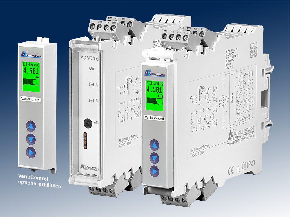
| Input current |
|---|
| Measuring range |
-24 ... + 24 mA DC |
| Input resistance |
20 Ohm |
| Basic accuracy |
4 µA |
| Transmitter supply |
|---|
| Off-load voltage |
24,0 V |
| Voltage at 20mA |
18,0 V |
| Current limit |
~ 25 mA |
| Input voltage |
|---|
| Measuring ranges |
0 ... + 12 V DC |
| Input resistance |
1 MOhm |
| Basic accuracy |
1 mV |
| Input voltage mV |
|---|
| Measuring ranges |
-15 ... +15 mV |
|
-30 ... +30 mV |
|
-60 ... +60 mV |
|
-125 ... +125 mV |
|
-250 ... +250 mV |
| Input resistance |
1 MOhm |
| Basic accuracy |
20 µV |
| Thermocouples |
|---|
| Comparative place: |
| Internal |
Measurement with sensor in the device connecting terminals |
| External |
Cold junction temperatureselectable by parameters |
| To DIN EN 60584: |
| Messbereich Typ J |
-200 ... +1200 °C |
| Messbereich Typ T |
-200 ... +400 °C |
| Messbereich Typ K |
-200 ... +1360 °C |
| Messbereich Typ E |
-200 ... +1000 °C |
| Messbereich Typ N |
-200 ... +1300 °C |
| Grundgenauigkeit |
1 K |
| To DIN EN 60584: |
| Messbereich Typ S |
-40 ... +1760 °C |
| Messbereich Typ R |
-40 ... +1760 °C |
| Messbereich Typ B |
+400 ... +1800 °C |
| Grundgenauigkeit |
2 K |
| After standard ASTM E988: |
| Messbereich Typ C |
0 ... +2320 °C |
| Grundgenauigkeit |
2 K |
| Resistance input |
|---|
| Resistance thermometer inputs DIN EN 60751: Pt100, Pt500 and Pt1000 DIN 43760: Ni100, Ni500 and Ni1000 |
| Messbereich Pt |
-200 ... +850 °C |
| Messbereich Ni |
-60 ... +230 °C |
| Kleinste Messspanne |
20 K |
| Kurzschlusserkennung |
< 20 Ohm |
| Grundgenauigkeit |
0,2 K |
| Linear resistance |
| Messbereich |
0 ... 4000 Ohm |
| Grundgenauigkeit |
0,1 Ohm |
|
| Connection method |
2-, 3- oder 4-wire system |
| Sensor supply |
100 µA |
| Max line resistance 1) |
50 Ohm/cable |
| 1) With 2-conductor the line resistance comes as an offset into the measurement.
|
| Potentiometer input |
|---|
| Connection method |
3-wire system |
| Max. Resistance |
50 Ohm ... 100 kOhm |
| Sensor supply |
<=500µA |
| Current outputs |
|---|
| Max. output range |
-21,5 ... 21,5 mA DC |
| Max. burden |
400 Ohm |
| Residual ripple |
20 µAss |
| Voltage outputs |
|---|
| Max. output range |
-10,5 ... 10,5 V DC |
| Min. burden |
10 kOhm |
| Residual ripple |
10 mVss |
| Relay outputs A/B |
|---|
| Contact type |
Potential free changeover |
| Max. AC-breaking capacity |
250 V AC, 2 A AC, 50Hz |
| Max. DC-breaking capacity |
50 V DC, 2 A DC |
| Switching operations |
| Mechanical |
107 |
| AC: 230V / 2A, cos(phi)=1 |
6 * 105 |
| AC: 230V / 2A, cos(phi)=0,4 |
2 * 105 |
| DC: 24V / 1A |
2 * 105 |
| Transmission behaviour |
|---|
| Linearity error |
< 0,2 % of the measuring range |
| Temperature influence |
+/- 120 ppm/K of the measuring range |
| Rise time |
500 ms (0...90 %, 100...10 %) |
| Rise time (temperature input) |
< 1s (0...90 %, 100...10 %) |
| Supply |
|---|
| Voltage range AC |
50 ... 253 V AC, 50/60 Hz |
| Voltage range DC |
20 ... 253 V DC |
| Nominal voltage AC / DC |
230 V AC / 24 V DC |
| Power consumption AC / DC |
5,2 VA / 3,2 W |
| Power consumption with operating module AC / DC |
5,4 VA / 3,6 W |
| Housing |
|---|
| Dimensions (WxHxD) |
23x110x134 mm |
| With operating module (bxhxt) |
23x110x138 mm |
| Type of protection |
IP 20 |
| Connection method |
Detachable terminal clamp |
| Terminals, wire cross section |
2,5 mm² flex wire / 4 mm² one wire |
| Bolting torque terminals |
0,5 Nm |
| Weight |
~ 150 g |
| Manner of fastening |
35 mm DIN rail 35mm |
| Environmental conditions |
|---|
| Ambient temperature |
-10 ... 70 °C |
| Storage and transport |
-20 ... 70 °C (no condensation) |
| EMC |
|---|
| Product family standard 1) |
EN 61326-1 |
| Emitted interference |
EN 55011, CISPR11 Cl. B, Gr. 1 |
| 1)During electromagnetic disturbance minor changes in output signal are possible. |
| Electrical safety requirements |
|---|
| Product family standard |
EN 61010-1 |
| Overvoltage category |
II |
| Pollution degree |
2 |
| Galvanic isolation, test voltages |
|---|
| Input to output |
2,5 kV (1 min) |
| In-/output to auxiliary voltage |
4 kV (1 min) |
| Max. permanent working voltage |
Max. 300 V ACeff/DC |

