AD-BS 1 ST, AD-BS 2 ST, AD-BS 3 ST

Description

The overvoltage protection elements AD-BS1 ST, AD-BS2 ST and AD-BS3 ST have been designed for the protection of low voltage signal lines (e.g. 0/4...20 mA, 0/2...10V etc.). The overvoltage pulses can be caused e.g. by lightning strikes, switching operations in the power grid, inductive interference or static discharges. A special L-type is also available, which has inductors instead of resistors as longitudinal current limitation. This allows the voltage drop at the longitudinal protection to be significantly reduced and the signal to be protected to be less loaded. Due to the plug-in module design, the overvoltage protection elements can be easily replaced after response or during revision. After the protective element has been removed, the signal path is interrupted. Thus, operation without a protective element is not possible.
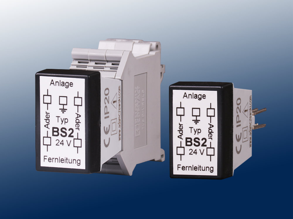
AD-BS 1 ST, AD-BS 2 ST, AD-BS 3 ST

Application

Protection of technology connected to low voltage signal lines against overvoltage surges.

Specific characteristics

  • Plug-in module technology
  • Standard Phoenix plug-in socket

Business data

Order number
AD-BS 1 ST Grobschutz ohne Längsstrombegrenzung
AD-BS 2 ST Grob- und Feinschutz mit Längsstrombegrenzung durch Widerstände
AD-BS 2 ST-L Grob- und Feinschutz mit Längsstrombegrenzung durch Induktivitäten
AD-BS 3 ST Grob- und Feinschutz mit Querspannungsbegrenzung und Längsstrombegrenzung durch Widerstände
AD-BS 3 ST-L Grob- und Feinschutz mit Querspannungsbegrenzung und Längsstrombegrenzung durch Induktivitäten
Identifiers
Customs tariff number / country of origin 8536 30 10 / Deutschland

Information

Technical specifications

General
Weight ~ 120 g
Mounting type DIN rail 35mm 35 mm
Ambient temperature -20 ... 60 °C
Type of protection IP20
Connection method Screw clamp
Conductor cross section 2,5 mm² Strand with wire end ferrule / 4 mm² one wire
AD-BS 1 ST
Rated voltage wire to earth 90 V
Output voltage limitation At 1 kV/ms: < 450 V
Series resistance per wire 0 Ohm
Max rated current per wire 2 A
Rated leakage current per wire 10 kA (8/20 pulse)
Response time < 100 ns
AD-BS 2 ST
Rated voltage wire to earth 22 V
Protective voltage wire to earth 25 V
Series resistance per wire 22,1 Ohm
Max rated current per wire 100 mA
Rated leakage current per wire 10 kA (8/20 pulse)
Response time < 0,10 ns
Other protection voltages 33 V, 50 V
Line inductance for L-type 40 uH
AD-BS 3 ST
Rated voltage wire to earth 22 V
Cross-voltage limitation (nominal) Wire against wire 22 V
Protective voltage wire to earth 25 V
Cross-voltage limitation (protection) wire against wire 25 V
Series resistance per wire 22,1 Ohm
Max rated current per wire 100 mA
Rated leakage current per wire 10 kA (8/20 Impuls)
Response time < 0,1 ns
Other protection voltages 33 V, 50 V
Line inductance for L-type 40 uH

Block and wiring diagram

AD-BS 1 ST, AD-BS 2 ST, AD-BS 3 ST

Dimensions

AD-BS 1 ST, AD-BS 2 ST, AD-BS 3 ST

Circuit examples

AD-BS 1 ST, AD-BS 2 ST, AD-BS 3 ST

CAD / CAE Daten

CAD model is not yet available for this product.

The CAD product overview can be found at: adamczewski.partcommunity.com

Attention

Input side is where overvoltage is expected (remote line). Output side points to the protecting installation. Earth connection is to be connected directly to the designating terminal. Avoid capacitive and inductive couplings, i.e. do not lay unprotected lines near the protected lines.

Cookie settings
made with ♡ by andres.media