AD-DTR 100 GVF

Description

The differential temperature controller DTR 100 GVF is designed for use in cooling systems for server cabinets or similar systems. With the help of this device system temperatures are regulated and therefore kept stable. The DTR 100 GVF takes two temperatures with the help of his two PT1000 sensor inputs and calculates the temperature difference to regulate the temperature with PI behavior. There are two analog outputs, with which an electric actuator with analog input can be controlled. No external 24V power supply must be set for the supply of this actuator because the DTR 100 GVF has an integrated short-circuit proof power supply for the supply of such an actuator. In addition, the controller includes digital signal inputs and relay outputs. Thus, digital states can be captured or redirected. Alternatively, a digital input can be used for the frequency measurement. Pulse of fans or pumps can be evaluated for speed detection. All analog values and digital states are available via Modbus RTU protocol. Connection of several devices on a bus is possible. This simplifies the monitoring of large installations significantly. For parameterization the DTR 100 GVF includes a front mounted control panel with color LCD screen.
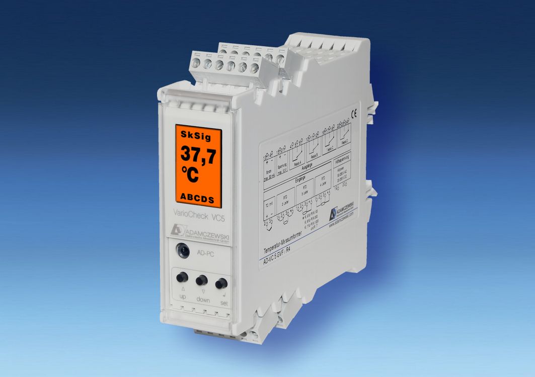
AD-DTR 100 GVF

Application

regulation of system temperatures in server cabinets or similar systems

Specific characteristics

  • 2 PT1000 inputs
  • current and voltage output
  • 4 digital inputs
  • 2 relay outputs
  • RS485-bus
  • integrated 24 V DC power supply for external actuator
  • detachable screw terminals
  • LC-Display

Business data

Order number
AD-DTR 100 GVF

Information

Downloads
Safety instructions pdf ad-safety-instructions.pdf (43 kB)

Technical specifications

Temperature inputs
Measuring range 0 ... 120 °C
Sensor type PT1000
Connection type 2-wire system (max. 20 m)
Resolution 12 Bit
Digital inputs
Nominal voltage 24 VDC
Max. voltage 30 VDC
Input resistance Ca. 2 kOhm
Frequency input
Measuring range 1 Hz ... 10 kHz
Resolution 1 Hz
Input level 24 V DC (square-wave)
Max. input voltage 30 V DC
Output current
Output range 0/4 ... 20 mA
Max. burden 400 Ohm
Residual ripple 20 µAss
Resolution 12 Bit
Output voltage
Output range 0/2 ... 10 V
Min. burden 1 kOhm
Residual ripple 10 mVss
Resolution 12 Bit
Relay outputs
Maximum switching load AC 250 V, 2 A
Maximum switching load DC 50 V, 2 A
Contact construction Potential-free changeover
Switching operations mechanical 10000000
At 230V/2A AC, cos(phi)=1 600000
At 230V/2A AC, cos(phi)=0,4 200000
At 24V/1 A DC 200000
RS485-Bus
Software protocol Modbus-RTU
Preset data format 19200,e,8,1
Max. bus users 255
Bus termination 120 Ohm at both sides (not integrated)
Max. length of bus 500 m (no stubs)
Cable Twisted and shielded
24 V DC output
Nominal voltage 24 V DC
Max. power delivery 3 W
Full load voltage Ca. 23 V DC
Open-circuit voltage Ca. 24,5 V DC
Residual ripple Max. 100 mVss
Supply
Voltage range AC 230 V AC +/- 10%, 50/60 Hz
Nominal voltage AC 230 V AC
Power consumption AC 7 VA
Transmission behaviour
Basic accuracy < 0,5 %
Temperature influence 100 ppm/K
Response time ~ 0,5 s
Housing
Dimensions (WxHxD) 30x110x134 mm
Type of protection IP 20
Connection method Detachable terminal clamp
Terminals, wire cross section 2,5 mm² flex wire / 4 mm² one wire
Bolting torque terminals 0,5 Nm
Weight ~ 250 g
Manner of fastening 35 mm DIN rail 35mm
Environmental conditions
Ambient temperature -10 ... 60 °C
Storage and transport -20 ... 70 °C (no condensation)
EMC
Product family standard EN 61326 1)
Emitted interference EN 55011, CISPR11 Cl. B
Electrical safety requirements
Product family standard EN 61010-1
Overvoltage category II
Pollution degree 2
Galvanic isolation, test voltages
Low voltage / relay output 4 kV, 50 Hz (1 min.)
Low voltage / power supply 4 kV, 50 Hz (1 min.)
Protection circuits
Input Electrical surge protection
Output Electrical surge protection
RS485-Bus Electrical surge protection
Power supply Protection against overvoltage, overcurrent and overtemperature
1) During checking, slight signal deviations are possible.

Block and wiring diagram

AD-DTR 100 GVF

Dimensions

AD-DTR 100 GVF

We only use technically necessary cookies to improve the user-friendliness of our site.
Cookies for analysis and marketing purposes are not used!
You can find further information in our privacy policy.
made with ♡ by andres.media