AD-ISW 100 GS

Description

The incremental setpoint generator is used to preset an analog value (0 / 4–20 mA, 0–10 V) with the aid of external control signals. The output range from 0–100% is divided into 256 steps. The output change by one step is carried out by an input pulse of at least 64 ms in length. With a continuous signal, there is an automatic change approx. every 282 ms by one step (ramp function). An infinite ramp function when the signal direction is reversed at the range limits can be configured. Potential-free contacts as well as active voltages of 5–30 V DC can be used as input pulse sources. The signal setting can also be made with the two device buttons. Pressing both buttons at the same time for approx. 2 seconds saves the instantaneous value as the start value after a supply voltage failure. The storage process is acknowledged by blanking the operating voltage LED. There is a red LED for each signal direction input, which indicates the active input status. During the ramp function, the respective LED flashes according to the direction of change. The output signal is galvanically separated from the active inputs and also from the supply voltage.
The following can be configured using AD Studio software:
- Number of steps (2 ... 1000)
- Time interval per step (10 ... 2000 ms)
- Area limits
- Ramp function
- Signal start values
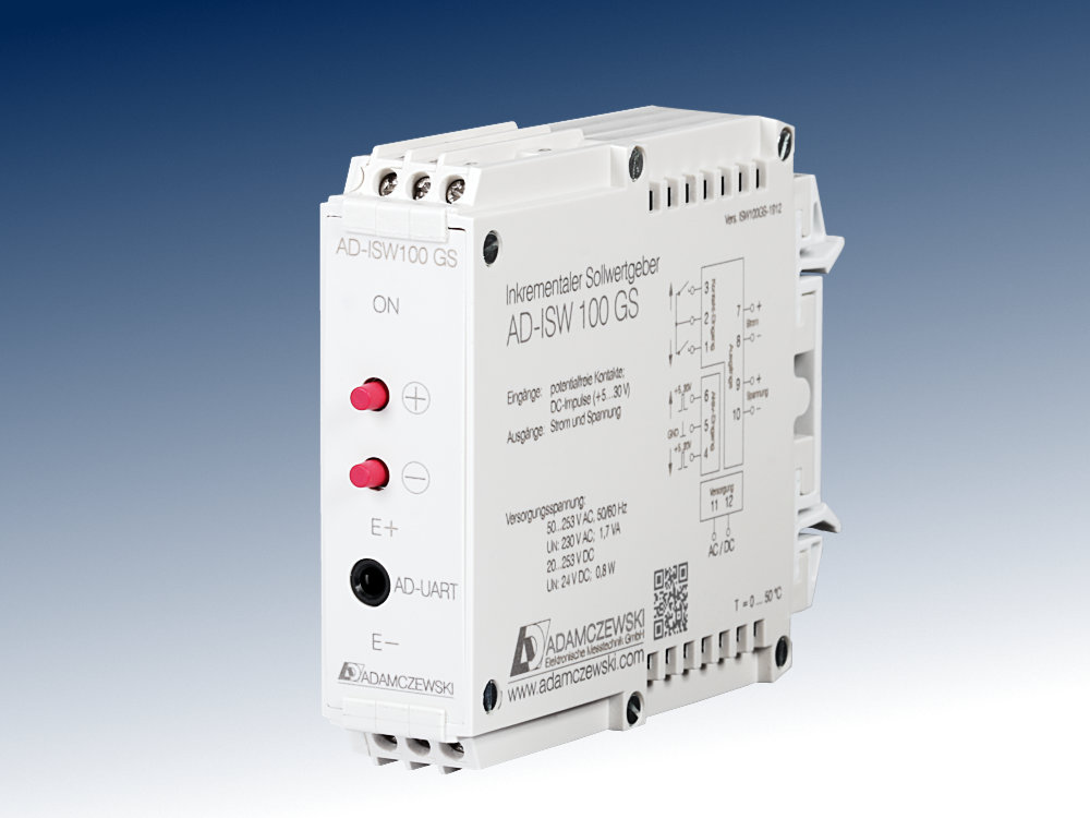
AD-ISW 100 GS

Application

Presetting of analog values by means of external control signals (contact or DC voltage).

Business data

Order number
AD-ISW 100 GS
Identifiers
Customs tariff number / country of origin 8538 90 91 / Deutschland

Information

Downloads
Data sheet pdf en-isw100gs.pdf (171 kB)
Safety instructions pdf ad-safety-instructions.pdf (43 kB)

Technical specifications

Contact
Feeding voltage 5 V
Current limit ~ 3 mA
Input voltage
Input level 0 / 5 ... 30 V
Input resistance 3 kOhm
Input signals
Minimum pulse width 64 ms
Contact debouncing 50 ms
Ramp start > 2000 ms
Step time 282 ms 1)
Step size 1 / 256 1)
Output current
Output range 0...20 mA; 4...20 mA 1)
Max. burden 500 Ohm
Max. residual ripple 40 µAss
Open-circuit voltage < 13 V
Output voltage
Output range 0...10 V; 2...10 V 1)
Min. burden 10 kOhm
Max. residual ripple 20 mVss
Current limit < 40 mA
Supply
Voltage range AC 50 ... 253 V AC, 50/60 Hz
Nominal voltage AC 230 V AC
Voltage range DC 20 ... 253 V DC
Nominal voltage DC 24 V DC
Input power AC/DC 1,7 VA / 0,8 W
Signal behavior
Resolution 11 Bit
Basic accuracy < 0,2 %
Temperature influence 100 ppm/K
Housing
Dimensions (WxHxD) 23x78x103 mm
Type of protection IP 20
Connection method Screw clamp
Terminals, wire cross section 2,5 mm² flex wire / 4 mm² one wire
Bolting torque terminals 0,5 Nm
Weight ~ 100 g
Manner of fastening 35 mm DIN rail 35mm
Environmental conditions
Ambient temperature -10 ... 50 °C
Storage and transport -10 ... 70 °C (no condensation)
EMC
Product family standard EN 61326-1 2)
Emitted interference EN 55011, CISPR11 Cl. B, Gr. 1
Electrical safety requirements
Product family standard EN 61010-1
Overvoltage category II
Pollution degree 2
Galvanic isolation, test voltages
Contact / Output No
Active input / Output 1,0 kV, 50 Hz (1 min.)
Signal / supply unit 3 kV, 50 Hz (1 min.)
Protection circuits
Input Electrical surge protection
Output Electrical surge protection
Power supply Protection against overvoltage
reverse polarity
1) In/Out signals can be configured with AD studio software.
2) Slight signal deviations are possible during interference.

Block and wiring diagram

AD-ISW 100 GS

Dimensions

AD-ISW 100 GS

CAD / CAE Daten

CAD model is not yet available for this product.

The CAD product overview can be found at: adamczewski.partcommunity.com

Display and operating elements

On Power supply LED (green)
lights up in normal operation
Blanking when signal storage
(+) Direction key for signal change
(-) Direction key for signal change
E(+) red LED for signal direction pulse
E(-) red LED for signal direction pulse
AD-UART Communication interface for configuration
Cookie settings
made with ♡ by andres.media