AD-KAB 10 GX

Description

The AD-KAB10 GX provides a remote controllable relay switching contact (changeover contact). Remote control is via the RS-485 bus interface. The device communication is realized using the MODBUS RTU protocol.
The power supply and the RS485 bus connection is possible via the rear DIN rail connector. The device is equipped with two rotary coding switches with which the bus address can be set on the device.
The static contact control is carried out with a control value 0 or 1.
A pulse output function (with 1 Hz) is triggered with a control value of 1 to 255 and can be modified or stopped at any time with other values. An optical search function allows the localization of a single device in a device network when in a cabinet several devices are on a top hat rail. For this purpose, the green LED is set in a time-limited flashing mode, between 1 and 255 seconds.
For the relay, a defined start state can be set so that when the supply voltage returns after a power failure, a system can assume the desired start state.
The interface settings as well as the device address can be modified during operation by means of Modbus commands. All Modbus register addresses and associated commands are listed in the document attachment.
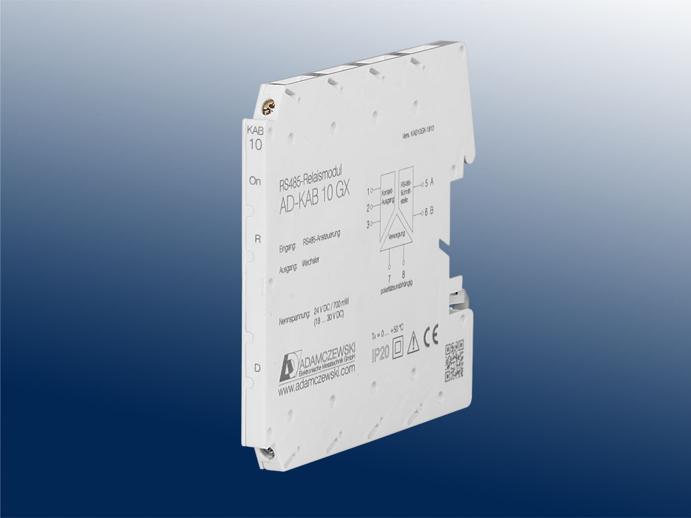
AD-KAB 10 GX

Application

Remote control of consumers such as valves or motors in building automation and automation technology.

Specific characteristics

  • RS485 bus / Modbus RTU protocol
  • Rotary coding switch for bus address setting
  • Presettable contact start state
  • Potential-free contact (changer)
  • Switching Power Supply
  • Pulse and toggle output function
  • Pulse summation (1/1000 + 1/100 + 1/10 + 1)
  • Optical search function, Modbus master mode

Business data

Order number
AD-KAB 10 GX
Accessory
Rail connector
(5-pin)
AD-GX-Connector
Identifiers
Customs tariff number / country of origin 8543 70 90 / Deutschland

Information

Downloads
Data sheet pdf en-kab10gx.pdf (206 kB)
Tender text zip kab10gx.zip (9 kB)
Safety instructions pdf ad-safety-instructions.pdf (43 kB)

Technical specifications

Relay
Maximum switching load AC 250 V, 2 A
Maximum switching load DC 50 V, 2 A
Contact construction Changeover contact
Switching operations mechanical 10000000
At 230V/2A AC, cos(phi)=1 500000
At 24V/1 A DC 1000000
Transmission behaviour
Response time Max. 15 ms
RS485-Bus
Software protocol Modbus-RTU
Data format 19200, e, 8, 1
Max. bus users 99
Bus termination 120 ohms both sides at the end
Max. length of bus 500 m (no spur lines)
Cable Twisted and shielded
Supply
Supply voltage 18 ... 30 V DC
Max. power consumption 700 mW (24V DC)
Housing
Dimensions (WxHxD) 6,2 x 92 x 101 mm³
Manner of fastening DIN rail mounting 35mm, EN 50022
Type of protection IP 20
Connection method Screw clamp
Bolting torque terminals 0,5 Nm
Wire cross section Max. 2,5 mm2
Weight ~ 70 g
Environmental conditions
Permissible ambient temperature -10 ... +50 °C
Storage and transport -10 ... +70 °C (no condensation)
EMC
Product family standard 1) EN 61326-1
Emission 2) EN 55011, CISPR11 Cl. A, Gr. 1
1) During checking, slight signal deviations are possible.
2) Warning:
This device is not intended to be used in residential areas and can not ensure adequate protection of radio reception in such environments.
Electrical safety requirements
Product family standard EN 61010-1
Galvanic isolation, test voltages
RS485 bus / power supply 1,5 kV, 50 Hz (1 min)
Relay contact 3 kV, 50 Hz (1 min)
Protection circuits
RS485-Bus Electrical surge protection
Power supply Electrical surge and reverse current protection

Block and wiring diagram

AD-KAB 10 GX

Dimensions

AD-KAB 10 GX

CAD / CAE Daten

CAD model is not yet available for this product.

The CAD product overview can be found at: adamczewski.partcommunity.com

Display and operating elements

Designation LED Meaning
On green Power supply
R red Relay state
D yellow RS485 Communication
RS485 Address switch(01...99)

Modbus Communication

The AD-KAB 10 GX has an RS485 bus interface on which the Modbus RTU protocol is used. All control functions of the device can be executed via this bus interface. The preset standard data format is 19200,e,8,1. Adaptation to a different data format is possible at any time. The bus address (1...99) is set to the side-mounted rotary switches. The address 0 is not permitted for the bus operation. However, on this zero position the device only via the standard data format (19200, e, 8.1) accessible. The position 0 thus represents a service position, the example can be used during parameterization error.

The AD-KAB 10 GX supports two Modbus functions. These are the functions "Read Holding Registers" (0x03) and "Write Holding Registers" (0x10). With the "Read Holding Registers" function data can be read from the device and written with "Write Holding Registers" data. The individual register width is 16 bits. Please see the Modbus specification for detailed explanations of the Modbus communication. This is online available for free, but can also be purchased from the Adamczewski homepage.

The following Modbus data are accessible via the RS485 bus:

Start address Reg. number Name Datatype [Code] = Value read write
40401 2 Pulse summation / 1 U32 0...4294967295 yes yes
40403 2 Pulse summation / 10 U32 0...4294967295 yes yes
40405 2 Pulse summation / 100 U32 0...4294967295 yes yes
40407 2 Pulse summation / 1000 U32 0...4294967295 yes yes
40501 1 Address switch U16 1...99...247 yes yes
40502 1 Output contact U16 0/1...255 yes yes
40503 1 Pulse output U16 1...255 yes yes
40504 1 Toggle relay U16 0/1 yes yes
40505 1 Flashing function U16 0/1...255 yes yes
40901 2 Scaling value float float no yes
44201 2 OFF limit float float yes yes
44211 2 ON limit float float yes yes
47215 2 Switching cycles U32 0... yes no
49102 1 Device reset U16 0 no yes
49105 6 Device type String KAB10GX yes no
49119 1 Firmware version U16 MSB/LSB yes no
42901 1 Baud rate U16 index, see list below yes yes
42902 1 Parity U16 [0]=even; [1]=odd; [2]=no yes yes
42903 1 Modbus Master U16 0/1 yes yes
42904 1 Relay start up state U16 0/1 yes yes


Coding baudrate list
Index 0 1 2 3 4 5 6 7 8 9
baud 2400 4800 9600 14400 19200 28800 38400 57600 76800 115200


After changing the interface parameters, a device reset is required.

Modbus master mode
The device can even work in Modbus master mode to transfer data between any devices within an RS485 line.
For Modbus master operation, starting with Modbus register 40611, there are 48 consecutive data transfer sets,
with 5 configuration registers each.

Start address Reg. number Name Datatype [Code] = Value read write
40611 1 Source address [1] U16 1...98 yes yes
40612 1 Source register [1] U16 nnnnn yes yes
40613 1 Target address [1] U16 1...99 yes yes
40614 1 Target register [1] U16 nnnnn yes yes
40615 1 Register count [1] U16 1/2 yes yes
40846 1 Source address [48] U16 1...98 yes yes
40847 1 Source register [48] U16 nnnnn yes yes
40848 1 Target address [48] U16 1...99 yes yes
40849 1 Target register [48] U16 nnnnn yes yes
40850 1 Register count [48] U16 1/2 yes yes


For the Modbus master mode, the parameter "Modbus master" must be activated and the address switch set to position 99.
Data transfer begins six seconds after activation or device restart.
A flashing green LED indicates a communication error.

Cookie settings
made with ♡ by andres.media