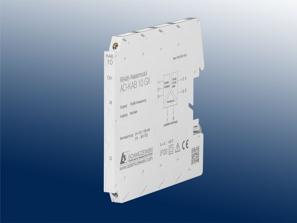
The AD-KEB 20 GX contains a RS485 bus interface on which the Modbus RTU protocol is used.
All control functions of the device can be executed via this bus interface.
The preset standard data format is 19200,e,8,1. Adaptation to a different data format is possible at any time.
The bus address (1...99) is set to the side-mounted rotary switches. The address 0 is not permitted for the bus operation.
However, on this zero position the device is accessible only via the standard data format (19200, e, 8.1).
The position 0 thus represents a service position, the example can be used during parameterization error.
The AD-KEB 20 GX supports two Modbus functions. These are the functions "Read Holding Registers" (0x03) and "Write Holding Registers" (0x10).
With the "Read Holding Registers" function data can be read from the device and written with "Write Holding Registers" data.
The individual register width is 16 bits. Please see the Modbus specification for detailed explanations of the Modbus communication.
This is online available for free and can be downloaded from the Adamczewski homepage.
The following Modbus data are accessible via the RS485 bus:
| Start address |
Reg. number |
Name |
Datatype |
[Code] = Value |
read |
write |
| 40501 | 1 | Address switch | U16 | 1...99...247 | yes | yes |
| 40502 | 1 | Flashing function | U16 | 0/1...255 | yes | yes |
| 40503 | 1 | 24V Input 1 | U16 | 0/1 | yes | no |
| 40504 | 1 | 24V Input 2 | U16 | 0/1 | yes | no |
| 40505 | 1 | Input contact 1 | U16 | 0/1 | yes | no |
| 40506 | 1 | Input contact 2 | U16 | 0/1 | yes | no |
| 40551 | 2 | Input frequency 1 | FLOAT | 0,00...2200 Hz | yes | no |
| 40553 | 2 | Input frequency 2 | FLOAT | 0,00...2200 Hz | yes | no |
| 42903 | 1 | Input signal type 1 | U16 | [0]=aktiv; [1]=Contact | yes | yes |
| 42904 | 1 | Input signal type 2 | U16 | [0]=aktiv; [1]=Contact | yes | yes |
| 43001 | 1 | Debouncing function 1 | U16 | 0/1 | yes | yes |
| 43002 | 1 | Debouncing function 2 | U16 | 0/1 | yes | yes |
| 47209 | 2 | Absolutely counter 1 | U32 | 0...4294967295 | yes | yes |
| 47211 | 2 | Absolutely counter 2 | U32 | 0...4294967295 | yes | yes |
| 47213 | 2 | Currently counter 1 | U32 | 0...4294967295 | yes | no |
| 47215 | 2 | Currently counter 2 | U32 | 0...4294967295 | yes | no |
| 42901 | 1 | Baud rate | U16 | Index, see list below | yes | yes |
| 42902 | 1 | Parity | U16 | [0]=even; [1]=odd; [2]=no | yes | yes |
| 42905 | 1 | Modbus master | U16 | 0/1 | yes | yes |
| 43003 | 1 | Modbus master idle time | U16 | 1...36 ms | yes | yes |
| 49102 | 1 | Device reset | U16 | 0 | no | yes |
| 49105 | 6 | Device type | String | KEB20GX | yes | no |
| 49119 | 1 | Firmware version | U16 | MSB/LSB | yes | no |
Coding baudrate list
| index |
0 |
1 |
2 |
3 |
4 |
5 |
6 |
7 |
8 |
9 |
| baud |
2400 |
4800 |
9600 |
14400 |
19200 |
28800 |
38400 |
57600 |
76800 |
115200 |
After changing the interface parameters, a device reset is required.
Modbus master mode
The device can even work in Modbus master mode to transfer data between any devices within an RS485 line.
For Modbus master operation, starting with Modbus register 40611, there are 48 consecutive data transfer sets,
with 5 configuration registers each.
Possible data type conversion (Target register count):
18 = INT to FLOAT
33 = FLOAT to INT
| Start address |
Reg. number |
Name |
Datatype |
[Code] = Value |
read |
write |
| 40611 | 1 | Source address [1] | U16 | 1...99 | yes | yes |
| 40612 | 1 | Source register [1] | U16 | nnnnn | yes | yes |
| 40613 | 1 | Target address [1] | U16 | 1...98 | yes | yes |
| 40614 | 1 | Target register [1] | U16 | nnnnn | yes | yes |
| 40615 | 1 | Register count [1] | U16 | 1/2/18/33 | yes | yes |
| 40846 | 1 | Source address [48] | U16 | 1...99 | yes | yes |
| 40847 | 1 | Source register [48] | U16 | nnnnn | yes | yes |
| 40848 | 1 | Target address [48] | U16 | 1...98 | yes | yes |
| 40849 | 1 | Target register [48] | U16 | nnnnn | yes | yes |
| 40850 | 1 | Register count [48] | U16 | 1/2/18/33 | yes | yes |
For the Modbus master mode, the parameter "Modbus master" must be activated and the address switch set to position 99.
Data transfer begins six seconds after activation or device restart.
A flashing green LED indicates a communication error.

