AD-LU 610 GT

Description

The digital power measuring transducer AD-LU 610 GT measures all quantities of the three-phase network (current, voltage, energy, harmonics, phase angle, active power, reactive power, apparent power etc.) and converts these measuring values onto two freely scalable analogue outputs (20 mA / 10 V). With the integral relay, the switching of limiting values or the output of energy pulses is possible. For output of more frequent energy pulses, the AD-LU 610 GT is alternatively also available with transistor output. The unit is therefore optimal suitable for integration in energy management systems. 3- or 4-wire systems can be measured.The AD-LU 610 GT is supplied via its measuring voltage L1. The current measuring is carried out via the bar-type transformer mounted on the front. For measuring of high voltages or high currents, external transformers can be connected in series at any time. The AD-LU 610 GT can be read out and parameterised via the integral RS485-interface with the aid of the available AD-Studio. A 96x96 mm TFT display module can also be connected to this interface. The LEDs at the front signals the operating condition, the RS485-data and the relay-status. The compact type of construction and the high performance ability with simultaneous low energy consumption allows usage in almost any application.
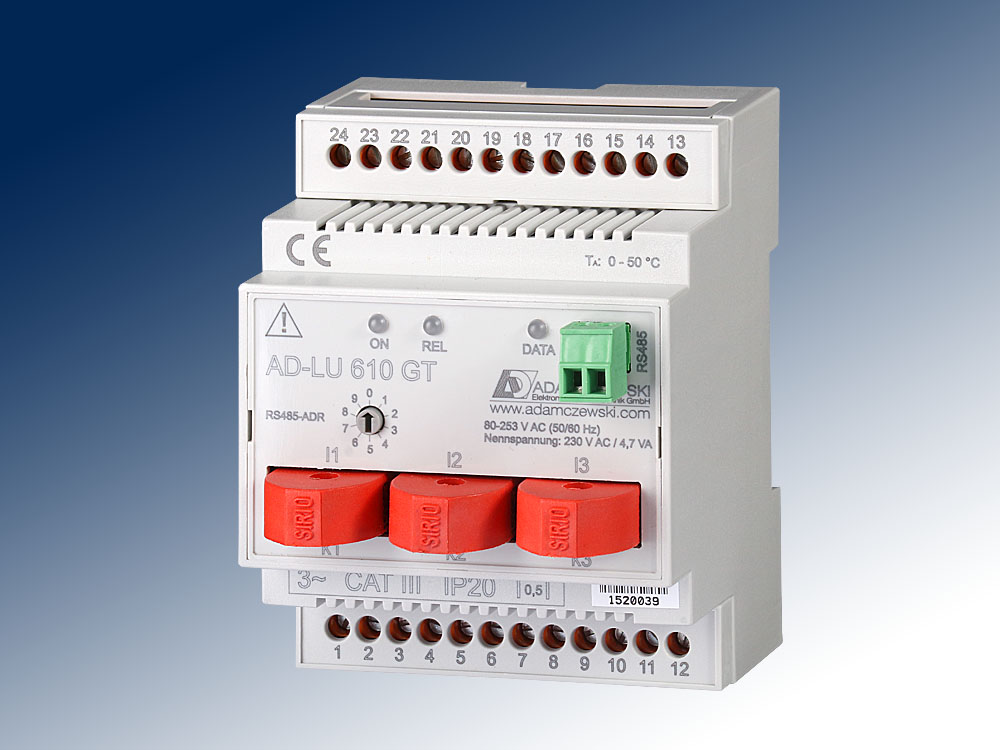
AD-LU 610 GT

Application

Typical usage in plant, machines or energy management systems for balancing and determination of energy distribution.

Specific characteristics

  • compact design
  • current measurement via clamp on current transfomrers
  • supplied via its measuring voltage L1
  • current and voltage output
  • relay or transistor output
  • monitoring all variables of the three-phase network
  • parameterization via AD-Studio
  • RS485 interface
  • TFT-Display AD-MM 400 connectable

Business data

Order number
AD-LU 610 GT Relay output
AD-LU 610 GT-O Transistor output
Accessory (optional)
VarioPass3 USB-inetrface adapter
AD-Studio Configuration software
AD-MM 400 TFT-Display
Identifiers
EClass 27210124
Customs tariff number / country of origin 8543 70 90 / Deutschland

Information

Downloads
Data sheet pdf en-lu610gt.pdf (397 kB)
Tender text zip lu610gt.zip (16 kB)
Safety instructions pdf ad-safety-instructions.pdf (43 kB)

Technical specifications

Current-inputs (I1...I3)
Measuring ranges 0 ... 1 A AC; 0 ... 5 A AC;
0 ... 20 A AC
Max. conductor diameter 4,8 mm
Max. measurable harmonic 40
Voltage-inputs (L1...L3)
Measuring range 80 ... 253 V AC
Input resistance > 900 kOhm
Output current
Output range 0/4 ... 20 mA
Max. load 400 Ohm
Resolution 11 Bit
Residual ripple 25 µAss
Output voltage
Output range 0/2 ... 10 V
Min. load 10 kOhm
Resolution 11 Bit
Residual ripple 30 mVss
Relay output
Maximum switching load AC 250 V, 2 A
Maximum switching load DC 50 V, 2 A
Contact construction Potential-free changeover
Switching operations mechanical 10000000
At 230V/2A AC, cos(phi)=1 600000
At 230V/2A AC, cos(phi)=0,4 200000
At 24V/2A DC 200000
Pulse length min ... max 500 ms ... 10000 ms
Alternative: transistor output
Maximum switching load DC 30 V, 50 mA
Pulse length min ... max 50 ms ... 10000 ms
Supply
Voltage range AC 80 ... 253 V AC, 50/60 Hz (see voltage-inputs)
Nominal voltage AC 230 V AC
Power consumption Max. 4,7 VA
RS485-Bus
Software protocol Modbus-RTU
Data format 19200, e, 8, 1
Address switch 0...9 (0: service position)
Bus termination 120 ohms both sides at the end
Max. length of bus 500 m (no stubs)
Cable Twisted and shielded
Transmission behavior - reference to full scale value
Basic accuracy < 0,5 % (class 0.5)
Temperature influence 80 ppm/K
Response time < 0,5 s
Housing
Dimensions (WxHxD) 71x90x70 mm
Type of protection IP 20
Connection method Screw clamp
Terminals, wire cross section 2,5 mm² flex wire / 4 mm² one wire
Bolting torque terminals 0,6 Nm
Skinning length 6 mm
Weight ~ 170 g
Manner of fastening 35 mm DIN rail 35mm
Environmental conditions
Ambient temperature -10 ... 50 °C
Storage and transport -10 ... 70 °C (no condensation)
EMC
Product family standard EN 61326-1 1)
Emitted interference EN 55011, CISPR11 Cl. B, Gr. 1
Electrical safety requirements
Product family standard EN 61010-1
Overvoltage category II
Pollution degree 2
Safety measurement EN 61010-2-030
Measurement category CAT III
Galvanic isolation, test voltages
Power supply to analog outputs 4 kV, 50 Hz (1 min.)
Power supply to relay 4 kV, 50 Hz (1 min.)
Relay to analog outputs 4 kV, 50 Hz (1 min.)
Protection circuits
Input Electrical surge protection
Power supply Protection against over-temperature, over-voltage and over-current
Analog outputs Electrical surge protection
1) During checking, slight signal deviations are possible.

Block and wiring diagram

AD-LU 610 GT

Dimensions

AD-LU 610 GT

CAD / CAE Daten

Under "Generate CAD", select the desired CAD model for this product.
For this purpose, registration with our CAD database "PARTcommunity" is required.
The complete CAD product overview can be found at: adamczewski.partcommunity.com

AD-LU 610 GT

Modbus Communication

The AD-LU 610 GT has a RS485 bus interface on which the Modbus RTU protocol is used. About this bus interface all measured data of the unit can be read out.
The default standard data format is 19200,e,8,1. Adaptation to a different data format is always possible.

data rate: 19200 baud (bits/s) parity: even data bit: 8 stop bit: 1

The bus address is set at the front mounted rotary switches. The address 0 is prohibited for bus application. However, on this zero position the device always uses the standard data format (19200, e, 8,1). The position 0 therefore represents a service position, can be used for example at incorrect parameterization.

The AD-LU 610 GT supports two Modbus functions. These are the functions "Read Holding Registers" (0x03) and "Write Multiple Registers" (0x10) . The function "Read Holding Registers" data can be read from the device and data is written with "Write Multiple Registers" . The individual register width is 16 bits.
Please refer to the Modbus specification for a detailed description of the Modbus communication. This is freely available online, but can also be obtained from the Adamczewski homepage.

The following Modbus data are accessible via the RS485 bus:

Messwerte:
start address no. of registers name unit data type read write
40501 2 TOTAL ACTIVE POWER kW 7 1 0
40503 2 PHASE A ACTIVE POWER kW 7 1 0
40505 2 PHASE B ACTIVE POWER kW 7 1 0
40507 2 PHASE C ACTIVE POWER kW 7 1 0
40509 2 TOTAL REACTIVE POWER kvar 7 1 0
40511 2 PHASE A REACTIVE POWER kvar 7 1 0
40513 2 PHASE B REACTIVE POWER kvar 7 1 0
40515 2 PHASE C REACTIVE POWER kvar 7 1 0
40517 2 TOTAL APPARENT POWER kVA 7 1 0
40519 2 PHASE A APPARENT POWER kVA 7 1 0
40521 2 PHASE B APPARENT POWER kVA 7 1 0
40523 2 PHASE C APPARENT POWER kVA 7 1 0
40525 2 TOTAL POWER FACTOR 7 1 0
40527 2 PHASE A POWER FACTOR 7 1 0
40529 2 PHASE B POWER FACTOR 7 1 0
40531 2 PHASE C POWER FACTOR 7 1 0
40533 2 TOTAL ACTIVE FUNDAMENTAL POWER kW 7 1 0
40535 2 PHASE A ACTIVE FUNDAMENTAL POWER kW 7 1 0
40537 2 PHASE B ACTIVE FUNDAMENTAL POWER kW 7 1 0
40539 2 PHASE C ACTIVE FUNDAMENTAL POWER kW 7 1 0
40541 2 TOTAL ACTIVE HARMONIC POWER kW 7 1 0
40543 2 PHASE A ACTIVE HARMONIC POWER kW 7 1 0
40545 2 PHASE B ACTIVE HARMONIC POWER kW 7 1 0
40547 2 PHASE C ACTIVE HARMONIC POWER kW 7 1 0
40549 2 PHASE A VOLTAGE RMS V 7 1 0
40551 2 PHASE B VOLTAGE RMS V 7 1 0
40553 2 PHASE C VOLTAGE RMS V 7 1 0
40555 2 N-LINE CALCULATED CURRENT RMS A 7 1 0
40557 2 PHASE A CURRENT RMS A 7 1 0
40559 2 PHASE B CURRENT RMS A 7 1 0
40561 2 PHASE C CURRENT RMS A 7 1 0
40563 2 CHANNEL A VOLTAGE PEAK V 7 1 0
40565 2 CHANNEL B VOLTAGE PEAK V 7 1 0
40567 2 CHANNEL C VOLTAGE PEAK V 7 1 0
40569 2 CHANNEL A CURRENT PEAK A 7 1 0
40571 2 CHANNEL B CURRENT PEAK A 7 1 0
40573 2 CHANNEL C CURRENT PEAK A 7 1 0
40575 2 FREQUENCY Hz 7 1 0
40577 2 PHASE A MEAN PHASE ANGLE ° 7 1 0
40579 2 PHASE B MEAN PHASE ANGLE ° 7 1 0
40581 2 PHASE C MEAN PHASE ANGLE ° 7 1 0
40583 2 MEASURED TEMPERATURE °C 7 1 0
40585 2 PHASE A VOLTAGE PHASE ANGLE ° 7 1 0
40587 2 PHASE B VOLTAGE PHASE ANGLE ° 7 1 0
40589 2 PHASE C VOLTAGE PHASE ANGLE ° 7 1 0
40591 2 VOLATGE L1 L2 V 7 1 0
40593 2 VOLATGE L2 L3 V 7 1 0
40595 2 VOLATGE L3 L1 V 7 1 0
40597 2 TOTAL ACTIVE FACTOR 7 1 0
40599 2 PHASE A ACTIVE FACTOR 7 1 0
40601 2 PHASE B ACTIVE FACTOR 7 1 0
40603 2 PHASE C ACTIVE FACTOR 7 1 0
40605 2 TOTAL REACTIVE FACTOR 7 1 0
40607 2 PHASE A REACTIVE FACTOR 7 1 0
40609 2 PHASE B REACTIVE FACTOR 7 1 0
40611 2 PHASE C REACTIVE FACTOR 7 1 0


List-parameters:
start address no. of registers name unit data type read write
41001 1 LIST_LOADTYPE 3 1 1
41003 1 LIST_BAUDRATE 3 1 1
41004 1 LIST_STOPBIT 3 1 1
41005 1 LIST_PARITY 3 1 1
41006 1 LIST_MEASSUREMENT_ASSIGNMENT_IOUT 3 1 1
41007 1 LIST_MEASSUREMENT_ASSIGNMENT_UOUT 3 1 1
41008 1 LIST_RELAY_FUNCTION 3 1 1
41009 1 LIST_MEASSUREMENT_ASSIGNMENT_REL_S0 3 1 1
41010 1 LIST_MEASSUREMENT_ASSIGNMENT_REL_LIMIT 3 1 1
41011 1 LIST_RELAIS_WORKING_TYPE 3 1 1
Data-parameters:
start address no. of registers name unit data type read write
41501 2 DATA_FILTER s 7 1 1
41503 2 DATA_PRIMARY_CURRENT A 7 1 1
41505 2 DATA_SECUNARY_CURRENT A 7 1 1
41507 2 DATA_PRIMARY_VOLTAGE V 7 1 1
41509 2 DATA_SECUNDARY_VOLTAGE V 7 1 1
41511 2 DATA_REL_SWITCH_ON_TIME V 7 1 1
41513 2 DATA_REL_SWITCH_OFF_TIME V 7 1 1
41515 2 DATA_REL_S0_PULSE_VALUE V 7 1 1
41517 2 DATA_REL_PULSE_LENGHT V 7 1 1
Counter:
start address no. of registers name unit data type read write
43503 2 COUNTER_KWH_TOTAL_CONSUPTION kWh 5 1 1
43505 2 COUNTER_KWH_TOTAL_INFEED kWh 5 1 1
43507 2 COUNTER_KVARH_TOTAL_INDUCTIVE kVarh 5 1 1
43509 2 COUNTER_KVARH_TOTAL_CAPACITIVE kVarh 5 1 1
43511 2 COUNTER_KVAH_TOTAL kVAh 5 1 1
43525 2 COUNTER_LOADHOURS kVAh 5 1 1


Legend of the Datatypes:
U08: 1 S08: 2 U16: 3 S16: 4 U32: 5 S32: 6 float: 7


Encoding of the list-parameters (list index:value):
load type 0:unequal 1:equal
baudrate 0:2400 1:4800 2:9600 3:14k4 4:19k2 5:28k8 6:38k4 7:57k6 8:76k8 9:115k2
stopbit 0:1 1:2
parity 0:even 1:odd 2:none
meass. assignm. Iout Index corresponds to measured value list: starting from 0
meass. assignm. Uout Index corresponds to measured value list: starting from 0
relay function 0:limit. 1:S0 2:window 3:energy -direction
meass. assign. Rel S0 0:Ptot C. 1:Ptot I. 2:Qtot L 3:Qtot C 4:Stot
meass. assign. Rel limit Index corresponds to measured value list: starting from 0
working type Rel 0:work 1:rest

Cookie settings
made with ♡ by andres.media