AD-MV 554 GT

Description

The 4-channel transmitter AD-MV 554 GT is a programmable measuring device for measuring resistance and millivolt signals. Thanks to the integrated function blocks and free linearization curves, the AD-MV 554 GT can be used universally, preferably for temperature measurement with temperature sensors. The measured values are accessed via appropriate registers using the Modbus RTU protocol. Device addresses from 1 to 99 can be set using the address switches accessible on the front. All parameters are set up via the RS485 interface using the "AD-Studio" PC configuration software. The interface parameters can also be set for inserting the devices into existing bus systems. The operating voltage is indicated by means of a green light-emitting diode. The data communication is signaled with a yellow light emitting diode. Invalid measuring signals outside the defined measuring range are detected. In this case the green LED flashes.
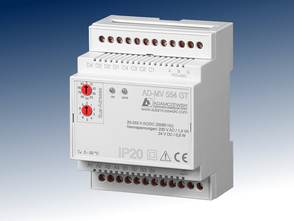
AD-MV 554 GT

Specific characteristics

  • Resistance thermometer inputs, types Pt/Ni 100, Pt/Ni 500, Pt/Ni 1000
  • Thermocouples inputs, types J, T, K, E, N, S, R, B, C or inputs a mV/T-characteristic curve. Selectable internal or external reference junction
  • A bipolar mV-Voltage input. Free linearizing curves possible.
  • Freely definable scaling of the quantity to be measured through stating range, decimal point position and unit from the list or defined unit.
  • Zoom function, expanded scale, linearizing, inverse modus.
  • Non-volatile saving of all set parameters.
  • 4 measuring channels

Business data

Order number
AD-MV 554 GT
Identifiers
EClass 27210129
Customs tariff number / country of origin 8543 70 90 / Deutschland

Information

Downloads
Data sheet pdf en-mv554gt.pdf (300 kB)
Safety instructions pdf ad-safety-instructions.pdf (43 kB)

Technical specifications

Resistance thermometer inputs Pt100, Pt500, Pt1000 to DIN EN 60751
Measuring range -200 ... +850 °C
Connection method 2-, 3-, 4-wire system
Resolution 16 Bit
Accuracy 2 K
Smallest measuring spans 30 K
Max line resistance 1) 10 Ohm / cable
Sensor supply
For 4-wire connection < 500 µA
For 2 - and 3-wire connection < 250 µA
1) With 2-conductor the line resistance comes as an offset into the measurement.
Resistance thermometer inputs Ni100, Ni500, Ni1000 to DIN EN 43760
Measuring range -60 ... +230 °C
Connection method 2-, 3-, 4-wire system
Resolution 16 Bit
Accuracy 2 K
Smallest measuring spans 30 K
Max line resistance 1) 10 Ohm / cable
Sensor supply
For 4-wire connection < 500 µA
For 2 - and 3-wire connection < 250 µA
1) With 2-conductor the line resistance comes as an offset into the measurement.
Thermocouples
Comparative place:
Internal Measurement at device terminals
External Cold junction temperatureselectable by parameters
Resolution 16 Bit
Accuracy 0,2 % of measuring range
Measuring range type J -200 ... +1200 °C
To DIN EN 60584:
Measuring range type T -200 ... +400 °C
Measuring range type K -200 ... +1360 °C
Measuring range type E -200 ... +1000 °C
Measuring range type N -200 ... +1300 °C
Measuring range type S -40 ... +1760 °C
Measuring range type R -40 ... +1760 °C
Measuring range type B +400 ... +1800 °C
After standard ASTM E988:
Measuring range type C 0 ... +2320 °C
Smallest measuring spans 100 K
Voltage inputs
Measuring range -18 ... +18 mV
-36 ... +36 mV
-72 ... +72 mV
-144 ... +144 mV
Resolution 16 Bit
Accuracy 0,2 % of measuring range
Transmission behaviour
Sampling rate 1 measure / s
Temperature influence +/- 100 ppm / K of full scale
RS485-Bus
Software protocol Modbus-RTU
Data format 19200, e, 8, 1
Max. bus users 99
Bus termination 120 ohms both sides at the end
Max. length of bus 500 m (no spur lines)
Cable Twisted and shielded
LEDs
Green [On] Supply (blinking on error)
Yellow [DATA] RS485 Communication
Controls
Address switch 01 ... 99
Supply
Supply voltage 20 ... 253 V DC / 50 ... 253 V AC
Max. power consumption 0,6 W / 1,4 VA
Housing
Dimensions (WxHxD) 71 x 90 x 58 mm3
Manner of fastening DIN rail mounting 35mm, EN 50022
Type of protection IP 20
Connection method Screw clamp
Bolting torque terminals 0,5 Nm
Wire cross section Max. 2,5 mm2
Weight Ca. 30 g
Environmental conditions
Permissible ambient temperature -10 ... +50 °C
Storage and transport -10 ... +70 °C (no condensation)
EMC
Product family standard 2) EN 61326-1
Emitted interference EN 55011, CISPR11 Cl. B, Gr. 1
2) During electromagnetic disturbance minor changes in output signal are possible.
Electrical safety requirements
Product family standard EN 61010-1
Overvoltage category II
Pollution degree 2
Galvanic isolation, test voltages
Signal / supply unit 3 kV, 50 Hz (1 min.)
Signal / RS485 bus Nogalvanic isolation
Signal / Signal Nogalvanic isolation

Block and wiring diagram

AD-MV 554 GT

Dimensions

AD-MV 554 GT

CAD / CAE Daten

CAD model is not yet available for this product.

The CAD product overview can be found at: adamczewski.partcommunity.com

Modbus Communication

The AD-MV 554 GT has an RS485 bus interface on which the Modbus RTU protocol is used. About this bus interface all measured data of the device can be read. The preset standard data format is 19200,e,8,1. Adaptation to a different data format is possible at any time. The bus address (1...99) is set to the side-mounted rotary switches. The address 0 is not permitted for the bus operation. However, on this zero position the device only via the standard data format (19200, e, 8.1) accessible. The position 0 thus represents a service position, the example can be used during parameterization error.

The device parameters are set exclusively using ADAMCZEWSKI configuration software AD-Studio.

The AD-MV 554 GT supports the Modbus function Read Holding Registers (0x03). With the Read Holding Registers function data can be read from the device. The individual register width is 16 bits. Please see the Modbus specification for detailed explanations of the Modbus communication. This is online available for free.

The following Modbus data are accessible via the RS485 bus:

Readings

MB address Number Channel Name Unit Data type [Code] = Value read write
40211 1 A signal status A --- U16 0 / 1 / 2 / 4 yes no
40125 2 A signal value A °C / mV float ####,# yes no
40231 6 A scale unit A °C / mV string unit yes no
40121 2 A terminal temperature A °C float ##,#### yes no
40212 1 B signal status B --- U16 0 / 1 / 2 / 4 yes no
40151 2 B signal value B °C / mV float ####,# yes no
40234 6 B scale unit B °C / mV string unit yes no
40147 2 B terminal temperature B °C float ##,#### yes no
40213 1 C signal status C --- U16 0 / 1 / 2 / 4 yes no
40177 2 C signal value C °C / mV float ####,# yes no
40237 6 C scale unit C °C / mV string unit yes no
40173 2 C terminal temperature C °C float ##,#### yes no
40214 1 D signal status D --- U16 0 / 1 / 2 / 4 yes no
40203 2 D signal value D °C / mV float ####,# yes no
40240 6 D scale unit D °C / mV string unit yes no
40199 2 D terminal temperature D °C float ##,#### yes no

Cookie settings
made with ♡ by andres.media