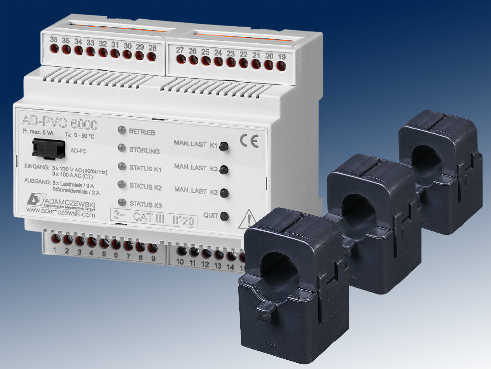
Operating LED
The green operating LED indicates the operating status of the device.
- off: the device has no operating voltage
- permanently on: the device is in normal operation mode
- flashing with 5 Hz: the manual load connection is active
Relay Status LEDs
- on: the load is connected to the device
- off: no load is connected
Error LED
The red error LED indicates whether an error is present.
- off: no error
- on: error is present
Key: Manual load (K1 ... K3)
The buttons "Manual load" serve the manual connection of the load relays. The load is activated with a long depression of the key (2s) and deactivated again the same way.
Key: Quit
The key "Quit" is provided for quitting an error message. If an error is present, the red error indicator LED lights up and the error message relay responds. An acoustic indicator can be connected at the error message relay, for instance. Now if the key "Quit" is activated, the relay releases again. The red error LED, however, is lit until the error has been eliminated.
Software and parameterizing
The device can be parameterized and read out with the parameterizing software AD-Studio and the optionally available USB programming adapter AD-VarioPass3. The suitable USB driver for the USB programming adapter AD-VarioPass2 is supplied with the software AD-Studio. With the software, measuring values can also be read out or logged.
For connecting to the PC, the blind plug must be removed from the parameterizing interface (AD-PC), i.e. with a small screwdriver. Push the screwdriver into the slot provided and work the blind plug out.
The following parameters can be edited:
- Filter: analogue value filter for the input measuring dimensions. Serves the suppression of quick measuring value alterations.
- Current transformer type: Specifies the connected current transformers type (distinguishing primary current).
- Power of the load (K1 ... K3): the power consumption at the load relays required by the connected load must be specified here. This specification is required for internal calculations.
- Switch-on-level (K1 ... K3): sets the switch-on threshold of the load relay, in reference to the fed power.
- Switch-off-level (K1 ... K3): Sets the switch-off threshold of the load relay, in reference to the fed power.
- Fault injection time: Sets the time, after which an alarm is triggered when during this set time no feeding has occurred.
- Plant size: Sets the plant size in kWp. Only used at 70%-message.
- Error relay function: Sets the function of the fault relay. You can choose between two modes: "feed-error" and "70%-message". The standard function "feed error" triggers a fault message after a specified time. This time is set in parameter "Fault injection time". The "70% message" triggers an alarm if all loads of the PVO are switched on and the PV-plant over 70% feeds. It is the "plant size" parameter evaluated.
- Operation Mode: Sets the operating mode of the device. In operating mode 0, the three load relays (K1, K2 and K3) are assigned with three output stages (example 500W, 1000W and 1500W) and they react in steps to the fed total output in all three phases. For the smallest switching stage, K1 must be selected and for the largest K3 must be selected.
In operating mode 1, each phase output is viewed separately and in each case one relay reacts to the relevant fed phase output (K1 to power in L1, K2 to power in L2 and K3 to power in L3).
With operating mode 2, three different loads are switched intelligently. That is, all possible combinations of the three loads are switched, to optimally implement the surplus energy. If, for instance, a heating rod has three heating coils with 500W, 1000W and 2000W, this results in seven combinations in steps of 500W. Here also the smallest load must be connected to K1 and the largest load must be connected to K3. In this operating mode, only the load capacity can be parameterized, the possible switching combinations and switching thresholds are calculated automatically.
Automatic load calibration
For commissioning the AD-PVO 6000, the parameters are normally adjusted via the parameterizing software AD-Studio and the available USB programming adapter AD-VarioPass3. However, an "automatic load calibration" can also be started directly at the device. In this operating mode, the output of the consumer connected to the load relays is automatically calibrated and a PC is not necessary. The load calibration is started with a longer depression of the "Quit-key" (3s). As long as the calibration is running, the two LEDs flash alternately. This process can last up to several minutes. If the calibration is cancelled with a brief depression of the "Quit-key", the values in the parameter are reset to the last status. After successful completion of the "automatic load calibration", the device takes over the measuring data and returns to normal operation. If the load calibration is not completed after approx. 15 minutes, there are too strong load fluctuations in the network. With too strong load fluctuations, the device is difficult to calibrate. Here we recommend to separate these loads briefly from the network during the calibration time, or to parameterize the device via the PC.
 Obsolescent model
