AD-VL 500 FE

Description

The AD-VL 500 FE monitor module is a display unit and data logger for front panel installation. It has up to 8 analogue standard signal inputs. The inputs can be configured as current or voltage inputs. Counter values can be derived simultaneously from the analogue signals by means of adjustable switching thresholds. A scaled measured value display with freely definable units is possible. The display is done by freely configurable display elements such as numeric display, bar graph, time diagram, drag pointer, LEDs, etc. The unit is supplied with predefined standard display windows. All signals can be logged cyclically in the unit's own memory. The logged data are stored as daily files on an internal micro SD card. They can be retrieved at any time with a USB stick or downloaded via the network interface. The unit can be configured either via the integrated web server of the network interface or via the configuration software AD-Studio. The configuration software is available free of charge on the ADAMCZEWSKI website. The various interfaces (RS485/LAN) make it easy to integrate the device into your own data networks in order to read out measurement data in real time.
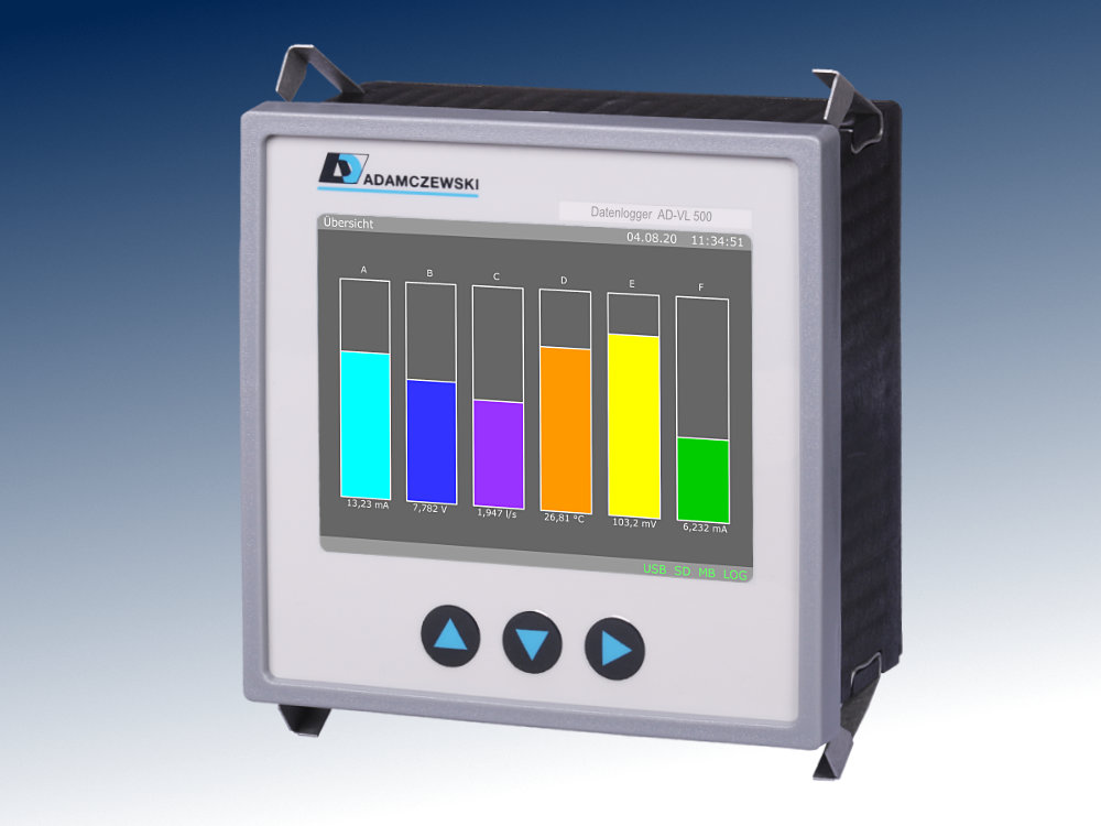
AD-VL 500 FE

Application

Display of freely definable values on a graphic display. Scrolling through several display types. Visual signal monitoring with web browser. Logging of data for later evaluation.

Specific characteristics

  • 40 configurable display elements.
  • All properties of the display elements such as colour, size, position, labelling and type are configurable.
  • 10 configurable displays with 1...12 display elements per display.
  • Integrated web server.
  • Convenient configuration of the displays via PC software AD-Studio.
  • Buffered real-time clock.
  • Interface protocols: Modbus-RTU, Modbus-TCP

Business data

Order number
AD-VL 500 FE
Identifiers
Customs tariff number / country of origin 8542 31 90 / Deutschland

Information

Downloads
Data sheet pdf en-vl500fe.pdf (139 kB)
Instruction manual pdf man-vl500-ad-en.pdf (3 MB)
Safety instructions pdf ad-safety-instructions.pdf (43 kB)

Technical specifications

Current inputs
Range 0 ... 20 mA
Resolution 14 bit
Input resistance 50 Ohm
Voltage inputs
Range 0 ... 10 V
Resolution 14 bit
Input resistance 100 kOhm
Counter
Range 0 ... 20 mA; 0 ... 10 ... 24 V
Input resistance I: 50 Ohm; U: 100 kOhm
Frequency < 1,5 Hz
Pulse width > 300 ms
Supply
Supply voltage 20 ... 253 V DC
Supply voltage 50 ... 253 V AC
Max. power consumption 3,0W / 9,5VA
Housing
Dimensions (WxHxD) 96x96x63 mm
Front panel cut out 92x92 mm
Protection class panel IP 54
Protection class connection IP 20
Connection method Detachable terminal clamp
Manner of fastening Panel-mount-case
Weight 250 g
Environmental conditions
Ambient temperature -10 ... 50 °C
Storage and transport -10 ... 70 °C (no condensation)
Pollution degree 2
EMC
Product family standard EN 61326-1
Emitted interference EN 55011, CISPR11 Cl. B, Gr. 1
Electrical safety requirements
Product family standard EN 61010-1
RS485-interface
Connection 3-pole socket 3.81mm
Standard RS-485
Protocol Modbus-RTU
Function Konfiguration, Modbus-Slave
Max. length of bus 100m - twisted, shielded cable
Bus termination 120 Ohm (both sites of the bus)
Configuration interface
Connection 3.5mm jack socket
Standard AD-PC (UART), proprietary
Function Configuration
Network interface
Connection RJ45 socket
Standard Ethernet, 10/100 Mbit/s
Protocol HTTP, Modbus-TCP
Function Web server, configuration, download
USB interface
Connection Type A socket for USB stick
Standard USB 1.0, 2.0
Function Data transfer
Display
Type 3,5 TFT
Resolution 320x240 Pixel
Operation
Type 3 short-stroke keys
Data logger
Internal memory size 2 GB
Internal storage medium µSD, single level cell
Sampling interval 1s ... ~18h
Max. channels 32
Data format *.csv (Text)

Block and wiring diagram

AD-VL 500 FE

Dimensions

AD-VL 500 FE

CAD / CAE Daten

CAD model is not yet available for this product.

The CAD product overview can be found at: adamczewski.partcommunity.com

Modbus-Data


Readings

Start address no. of registers name unit data type read write
40017 2 Analog value 1 mA/V float yes no
40019 2 Analog value 2 mA/V float yes no
40021 2 Analog value 3 mA/V float yes no
40023 2 Analog value 4 mA/V float yes no
40025 2 Analog value 5 mA/V float yes no
40027 2 Analog value 6 mA/V float yes no
40029 2 Analog value 7 mA/V float yes no
40031 2 Analog value 8 mA/V float yes no
40033 2 Scale value 1 float yes no
40035 2 Scale value 2 float yes no
40037 2 Scale value 3 float yes no
40039 2 Scale value 4 float yes no
40041 2 Scale value 5 float yes no
40043 2 Scale value 6 float yes no
40045 2 Scale value 7 float yes no
40047 2 Scale value 8 float yes no
40051 1 Digital level 1 0/1 U16 yes no
40052 1 Digital level 2 0/1 U16 yes no
40053 1 Digital level 3 0/1 U16 yes no
40054 1 Digital level 4 0/1 U16 yes no
40055 1 Digital level 5 0/1 U16 yes no
40056 1 Digital level 6 0/1 U16 yes no
40057 1 Digital level 7 0/1 U16 yes no
40058 1 Digital level 8 0/1 U16 yes no
40061 2 Counter value 1 U32 yes yes
40063 2 Counter value 2 U32 yes yes
40065 2 Counter value 3 U32 yes yes
40067 2 Counter value 4 U32 yes yes
40069 2 Counter value 5 U32 yes yes
40071 2 Counter value 6 U32 yes yes
40073 2 Counter value 7 U32 yes yes
40075 2 Counter value 8 U32 yes yes

Cookie settings
made with ♡ by andres.media